Introduction
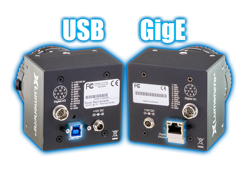
With camera sensors being able to transfer more and more data, choosing the right interface is crucial for any imaging application. Two popular interfaces are USB and GigE. Their cables and connectors have seen many changes over the years, so a comprehensive review of these interfaces and how they compare with modern sensor technology will help to illustrate the current state of interface technology.
Bandwidth
Understanding the bandwidth capabilities and requirements for imaging systems is critical for leveraging high resolution, better frame rates, and faster transfer speeds. The formula below can be used determine if an interface meets the requirements for the necessary bandwidth.
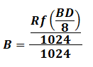
B: bandwidth.
R: pixel count; either resolution (pixel height multiplied by pixel width) or the megapixel value of a camera.
f: frame rate, which means how many images are being taken per second (i.e. 30 frames per second).
BD: bit-depth, values such as, 8, 10, 12, 14, and 16. These values are stored in memory in 8-bit portions, meaning anything after 8-bits up to 16-bits will have to be represented as 16-bit in memory.
The constant values used for division represent the following:
8: the conversion of the value of bits per second into bytes per second.
1024: converting bytes to kilobytes.
1024 again: kilobytes are converted into megabytes.
Here is a practical example for measuring the bandwidth needed for a vision system. A Teledyne Lumenera Lt945R camera, equipped with a 8.9 MP (megapixel) sensor, USB 3.1 Gen 1 (also known as USB 3.2 Gen 1) interface, with a frame rate of 19 fps (frames per second), taking 12-bit images, would require a 324 MB/s (megabytes per second) bandwidth. This bandwidth is below the maximum output for USB 3.1 Gen 1 (approximately 380 MB/s) which allows the interface to take full advantage of the sensor.
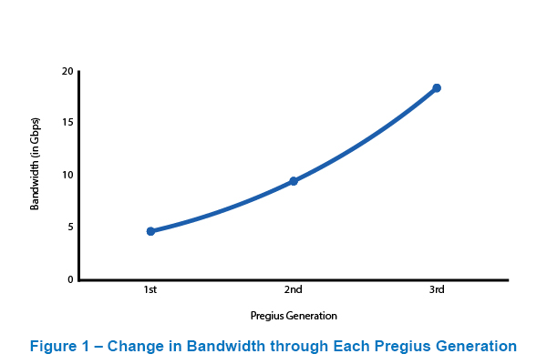
When considering what type of interface to use, a primary concern is bandwidth. It is crucial to ensure that a vision system can effectively transfer the high amount of data coming from modern sensor technology, such the Sony® Pregius™ or Starvis™ family of sensors. The actual bandwidth of sensors has continued to increase with each generation, as seen in Figure 1, with the Sony Pregius lineage. The first, second, and third generation of Pregius sensors has a bandwidth of 4.7, 9.5, and 18.4 Gbit/s (gigabits per second) respectively.
Interfaces
USB Interface
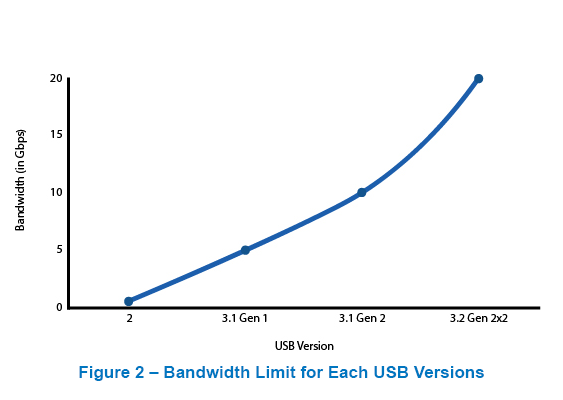
The USB standard started with USB 1.0 and at the time of writing this document has had many changes up to USB 3.2 Gen 2x2. An exponential increase in bandwidth can be seen in Figure 2, where each generation has at least doubled. Currently, USB 3 has 5, 10, and 20 Gbit/s versions which have gone through multiple name changes, while the still commonly used USB 2.0 standard has remained the same throughout its use.
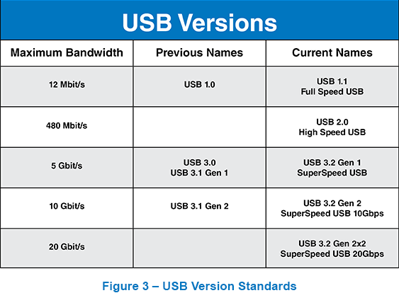
The original 5 Gbit/s standard for USB 3 has gone through more than one name change due to this trend. This has become somewhat confusing for many consumers trying to understand which name relates to which bandwidth. It should be noted that older USB version names are still used due to different hardware not always being updated as often as the USB standards. Below, Figure 3 displays the various USB versions with corresponding information.
The multiple types of USB connectors can be another point of confusion. However, there are certain types of connectors that are more common on lower end devices, while others can be found on higher end industrial products. For industrial purposes, the most common types of USB connectors are represented in Figure 4.
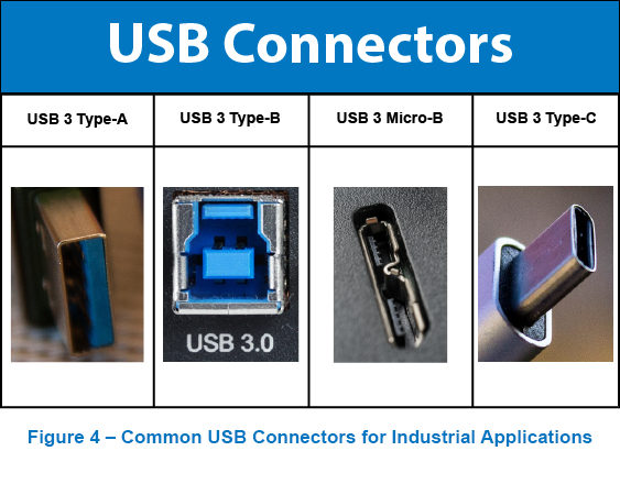
Other legacy USB connectors that are still found in many vision systems including: USB 2 Type-A, USB 2 Type-B, USB 2 Mini-B, and USB 2 Micro-B. Based on the size and shape of a device there are several more types of USB connectors that may apply.
GigE Interface
For applications where distance between the vision system and the destination (the server or computer to which the system is transferring data) is large, a GigE interface is likely the better solution. Unlike USB which has a 10 foot maximum cable length, GigE connections can extend to 100 feet. At a distance ten times longer, GigE cameras can be applied to a variety of long range applications such as factory automation or vision guided robotics.
Vision systems that use the 10 / 25 GigE interface require special equipment such as a server or network switch to process the specific protocol. A CAT6 cable is required when using a higher bandwidth GigE interface. This is different from the common CAT5 network cable found connected to most modems or routers in an office or at home. Due to the proliferation of the older CAT5 standard cables, a new standard was developed to maximize CAT5 performance. NBASE-T is a standard that is backwards compatible but is capable of 2.5 and 5 Gbit/s speeds. That means on older CAT5 cables speeds higher than the standard GigE bandwidth can be achieved, as seen in Figure 5.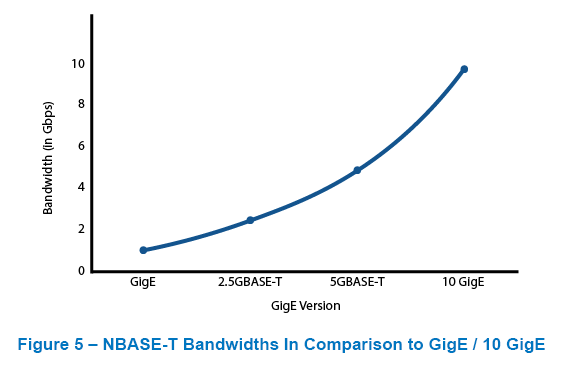
Using these newer standards can boost transfer speeds, but optimizing the hardware can give even faster frame rates. High frame rates can be especially important for high speed imaging in factories, such as with moving conveyer belts with many products or robotic systems interacting with moving objects. A drastic increase in frame rate can correspond to an equivalent increase in productivity with faster inspection and production equipment.
GigE Setup vs USB
As previously mentioned, GigE has an advantage when distance to the server / computer is a factor. However, USB is a more “plug-and-play” interface and results in a much simpler setup. A GigE device can require setting up an IP address and using up, for most computers, the only network port available for the device.
As mentioned previously, higher bandwidth GigE standards, such as 10 / 25 GigE require special cabling and equipment to function. On the other side, a USB device doesn’t require registering an IP address and most computers have several USB ports even on lower end devices.
However, with several GigE cameras connected to one network switch, the long cable lengths allow for flexible positioning throughout an area. In the case of a factory setting, these cameras can all be take high speed images of moving parts. These cameras can often be consolidated using a network switch to delegate each camera under the same interface.
Another advantage with GigE cameras is that the interface is easier to configure into custom connectors where wires need to be cut or crimped to fit a specific set up. Whether in a building with CAT 5 cables being managed throughout the facility or in the large structures of planes; adjustments to GigE connections are easy and is a go to interface for custom solutions.
Higher bandwidth standards
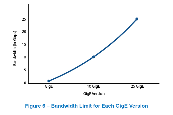
When considering what interface to use for a vision system it can be easy to simply choose the option with the higher bandwidth. However, even though USB 3 interfaces have a higher bandwidth than standard GigE, there are various GigE versions that can reach bandwidths up to 25 Gbit/s as shown in Figure 6 with standard GigE and 10 GigE for comparison.
The higher bandwidth standards for either interface are still relatively rare and are slowing being integrated into the market. The main issue with not implementing newer standards has to do with the time it takes for new framework to be designed by the various hardware manufacturers. Standards are being updated much more regularly than in previous years and manufacturers have to make choices on when to implement and which new standard to integrate with their products. Additionally, enough demand for newer standards needs to emerge in the market for manufacturers to divert research and development time away from other potential upgrades.
Overhead
The processing overhead for a specific interface does not usually make a noticeable difference in performance. However, for large scale applications such as using large imaging clusters for aerial imaging, a high level of accuracy is needed in order to create a mosaic. The processing unit of the vision system is critical in this type of application, but using a GigE interface puts a heavier load on the processor. Therefore, using a USB 3 interface is normally the optimal solution when the design of the system requires lower processing stress and can be optimized to use shorter cable lengths. For further information on mosaics and using multiple cameras for aerial imaging, read our white paper, "Using a Single Versus Multiple Cameras in Aerial Imaging."
Without the appropriate interface technology a vision system cannot meet its full potential. The challenge with choosing the right interface comes from the specific benefits each interface provides. Even with the increasing bandwidths, interfaces can only practically transfer a fraction of the sensors theoretical maximum bandwidth. The bandwidth speeds listed in Figures 2, 5, and 6 are actually the theoretical limits for each interface. Each device that implements a particular standard, such as USB 3 or GigE, will have some variation with what they are able to achieve in regards to a stable bit rate. Each devices needs to encode the information transmitted over the interface. This process is called processing overhead. This encoding results in the advertised or expected bandwidth for a particular device.
Power Requirements and added weight
The power requirements with using GigE are typically higher than USB. Therefore, GigE cameras may require external power supplies. However, many cameras can be powered over a USB connection or with power over Ethernet (PoE) which allows for the Ethernet cable to transmit both power and data over the same connection. On most large format cameras, USB or GigE will require an external power supply, but the higher amount of power draw from GigE cameras can results in draining more from a power supply unit (PSU).
In a weight-sensitive application like aerial imaging, a need for a more powerful PSU can mean adding bulk to an aircraft which can hinder airtime and flight capabilities due to added weight. This is particularly an issue for battery-powered UAVs that require the lightest design. However, it should be noted that the wiring for aircraft may be quite complicated and resulting in a need for longer cables to connect the PSU to the camera. In cases where the physical design requires longer cable length, a GigE interface may be a preferred option. For 10 GigE cameras that require extra hardware, the extra bulk and weight can be a significant problem for UAVs and may be out of the question in terms of the interface of choice.
Vision Standards
Due to the encoding over an interface such as USB3, transfer speeds end up averaging around 380MB/s instead of maximum supported within the 3.1 Gen 1 standards which is 625MB/s. It is important to consider these actual speeds when evaluating the various available options. Currently, the prominent standards adopted within vision system community include USB3 Vision and GigE Vision. The higher bandwidth option is USB3 Vision, which equates to the USB 3.1 Gen 2 standard for imaging applications. The USB3 Vision standard uses the GenlCam (Generic Interface for Cameras) standard, which is the typical underlying software interface for vision systems.
Conclusion
A diverse set of applications requires a diverse set of cameras. The ability to connect over long distances, minimize processing requirements, and maximize the amount of images being transferred, all comes from the option to find a vision system best suited to a particular application. For more information on what to look for in a camera, contact the Teledyne Lumenera imaging experts for a discussion on how to maximize imaging performance. Reach out at [email protected].
And, sign up for our newsletter to automatically receive regular updates from Teledyne Lumenera.
